
Watercooling Rack Controller
October 1, 2026
Intro
Firstly, hi! This is a bit meta but I'm going to use my most recent project here as a reason to write out my first blogpost. Not only do I just, want somewhere tidy to organize my projects (and I think blogs are great for that) I have just been getting a little sick of the 'modern internet' its all either entirely human, ie: private channels and chatrooms or.. its just a giant pile of AI slop
I miss personal websites.
So this is my project! I'm a human, I make things, I write code. Some of those things i make or write don't turn out very well but thats part of what makes things worth doing.
What am I making
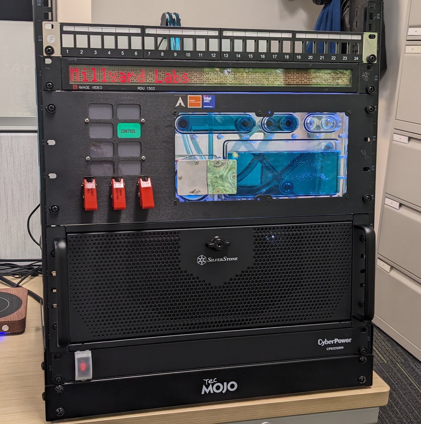
Spoilers: This is the final product. I've always wanted to build a PC into a rack, emphasis on PC. I've got plenty of full-sized servers in racks but thats a different sort of problem. I want the density and ease of access having just regular desktop style electronics in a rack provides.
This is my new-ish PC Silicon, and at the core is a Threadripper 7960. Amazing amazing CPU. I was only able to get it actually since i got the motherboard broken for a steal.
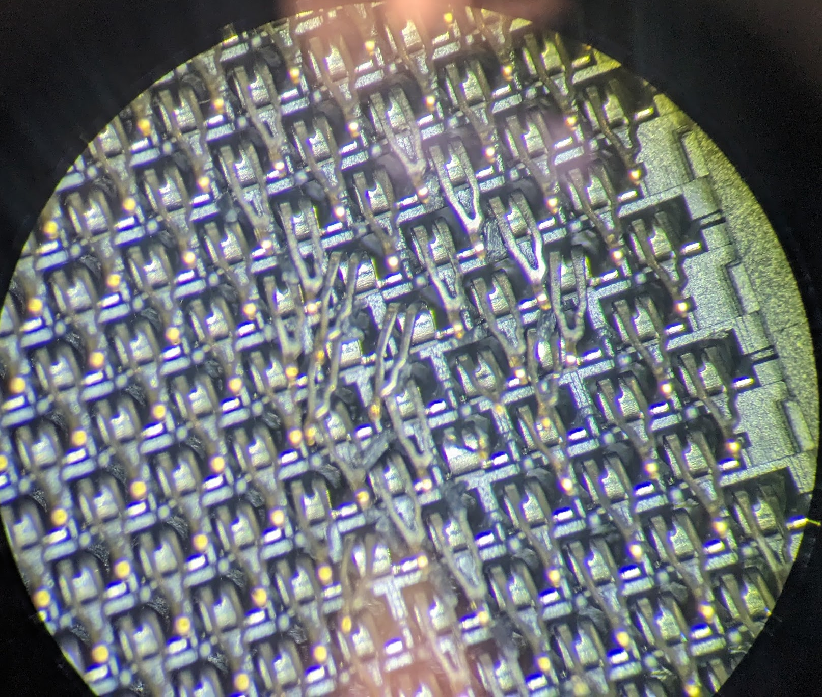
Thats a bit of a different topic though. Racks are amazing for storing a PC (or a multi-cpu pc like what i really want to build) but not exactly water cooling friendly.
I sorta mulled over a few options in my head, I could have one computer in the rack store a pump and res, radiator, basically package a regular desktop PC sideways and in a rack. But looking over options for cases quickly made that kinda tricky. Plus, then it relied on you having a particular PC powered up all the time. One that might not always be connected or installed if other things in the rack also need water cooling.
It sounds a little over-convoluted and maybe it is, but the solution i settled on was just to make my own rack unit that would go in the rack, manage cooling, fans, rads all on its own. Basically, just listen for the computer(s) installed in the rack to know when to fireup or cool down.
Manufacturing
Laser Cutting
I don't need to direct link this file but, at the same time I'm writing up this project I'm also testing out my website a little. So heres the 3d model for the faceplate
Obviously ofc, a direct link is better
I started first with a quick 3d print of the laser cut file
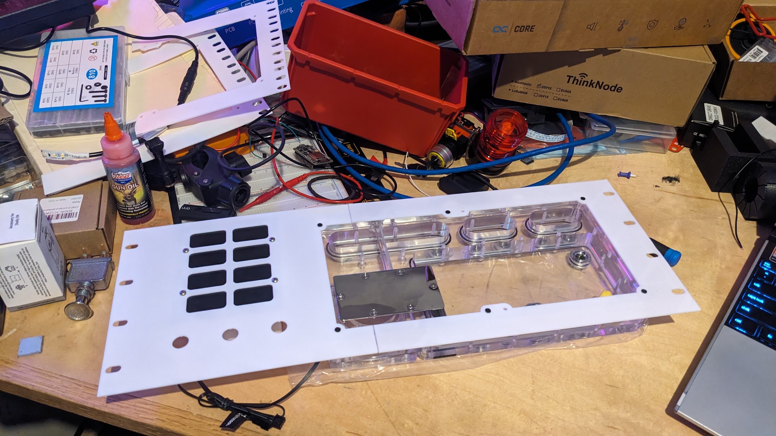
Apart from a few very minor tweaks I was actually pretty happy with the template off the bat.
I ordered the sheet metal from SendCutSend and asked them to anodize it black too, this was the first time i've had them do a finish.
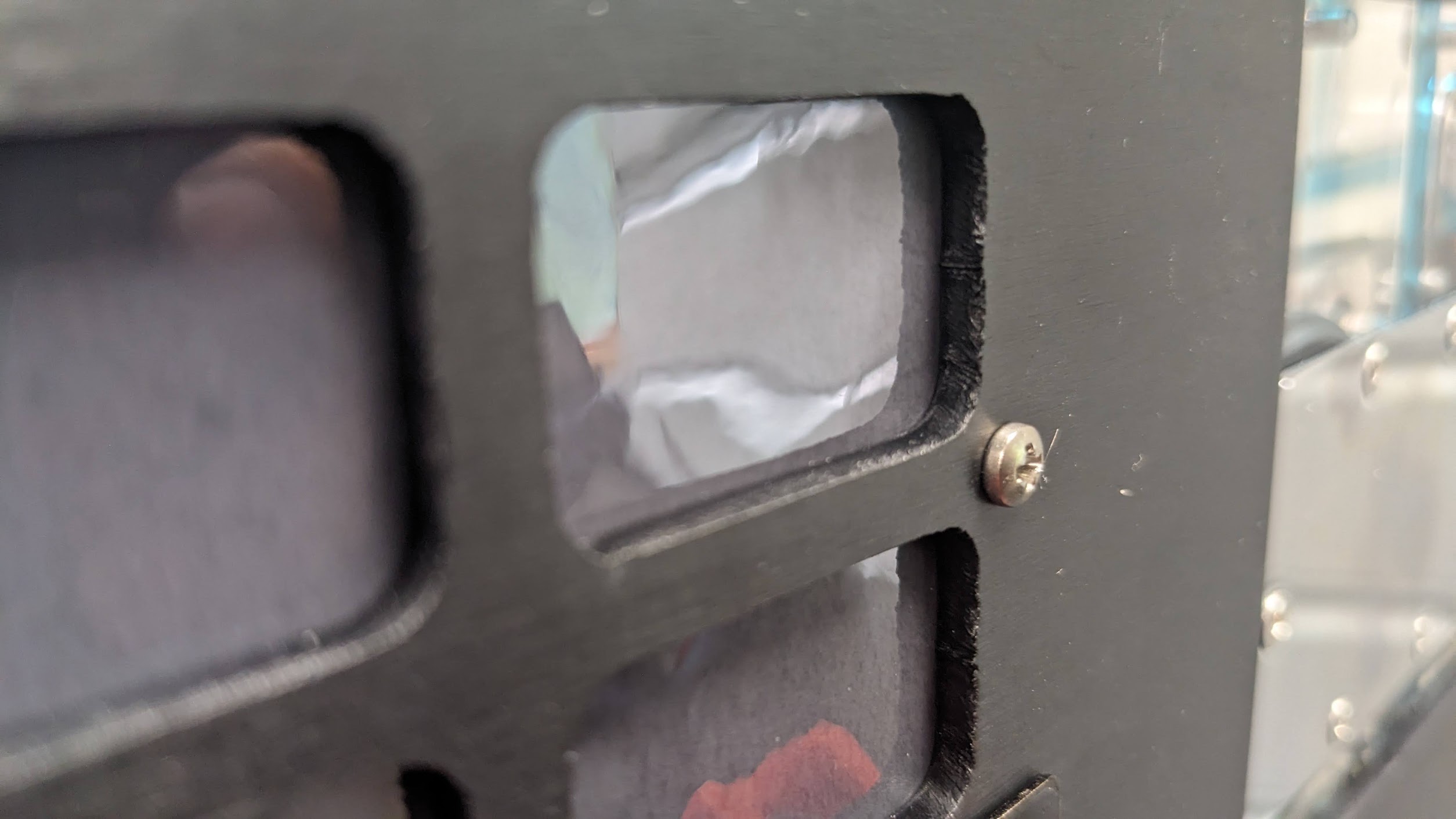
there were a few tiny defects but they actually ended up replacing the panel for free a few weeks later because of the defects so, +1 thanks SCS.
Making my displays
I had a couple ideas at the start. I knew i didn't want the indicators to be visible when the light was off, so one-way plastic or window tint was my inital idea. In hindsight i started too dark, 5% or 10% was just too black to see with any real brightness.
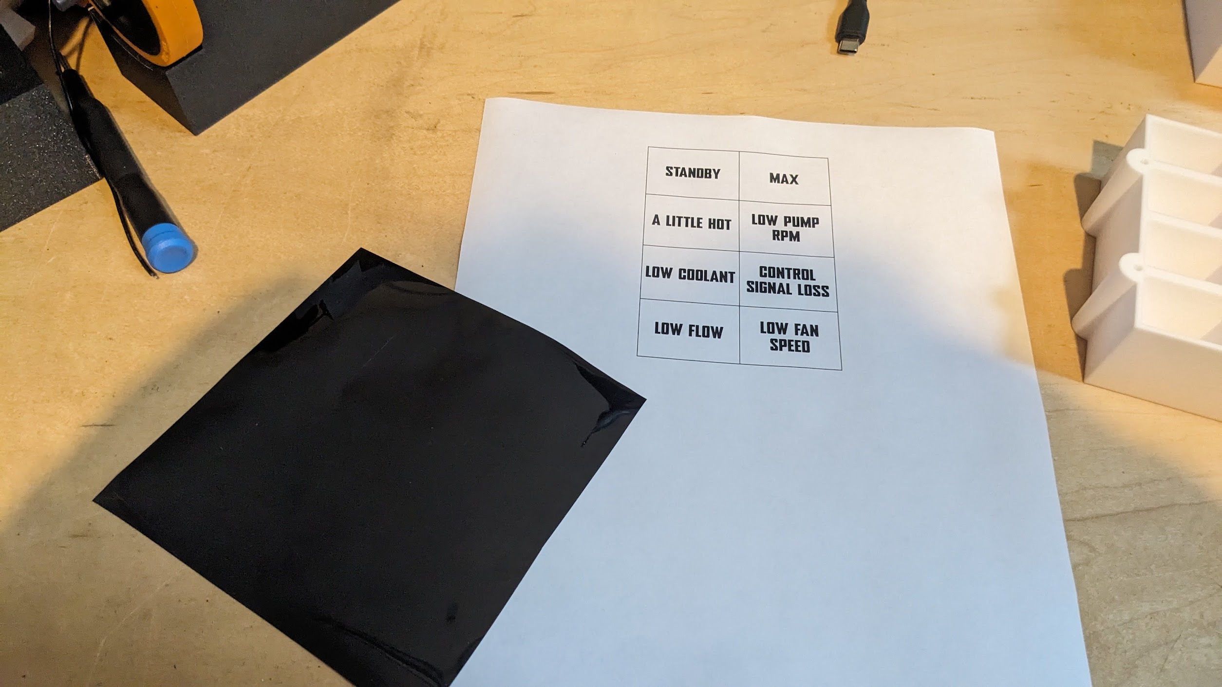
For my first attempt, I printed the indicators and pasted the sheet directly on top
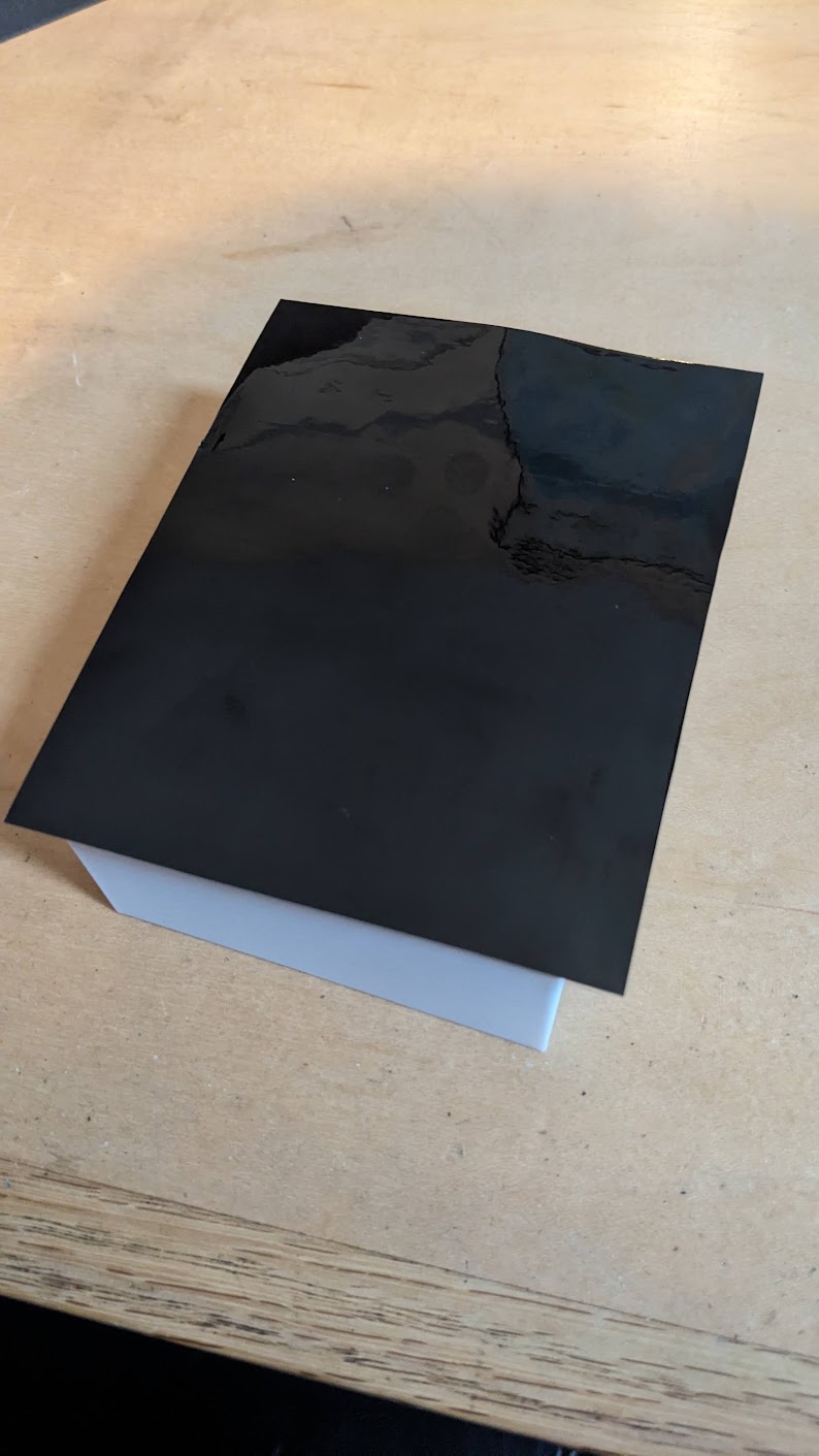
You can see how they peek through the mask down here
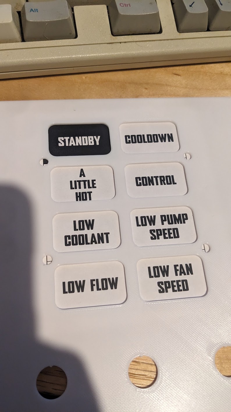
Worked well enough for the blinding white light but not much else
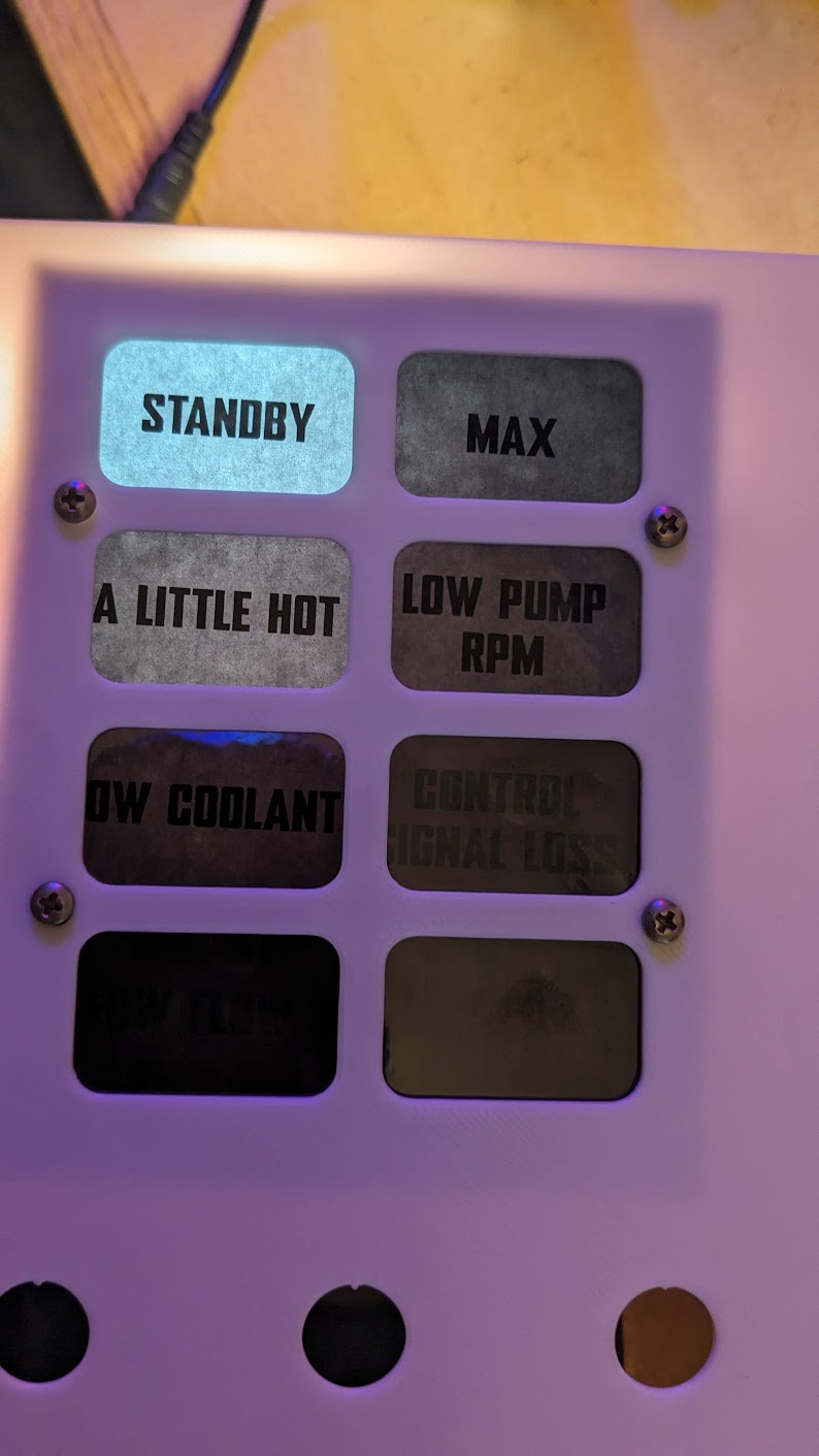
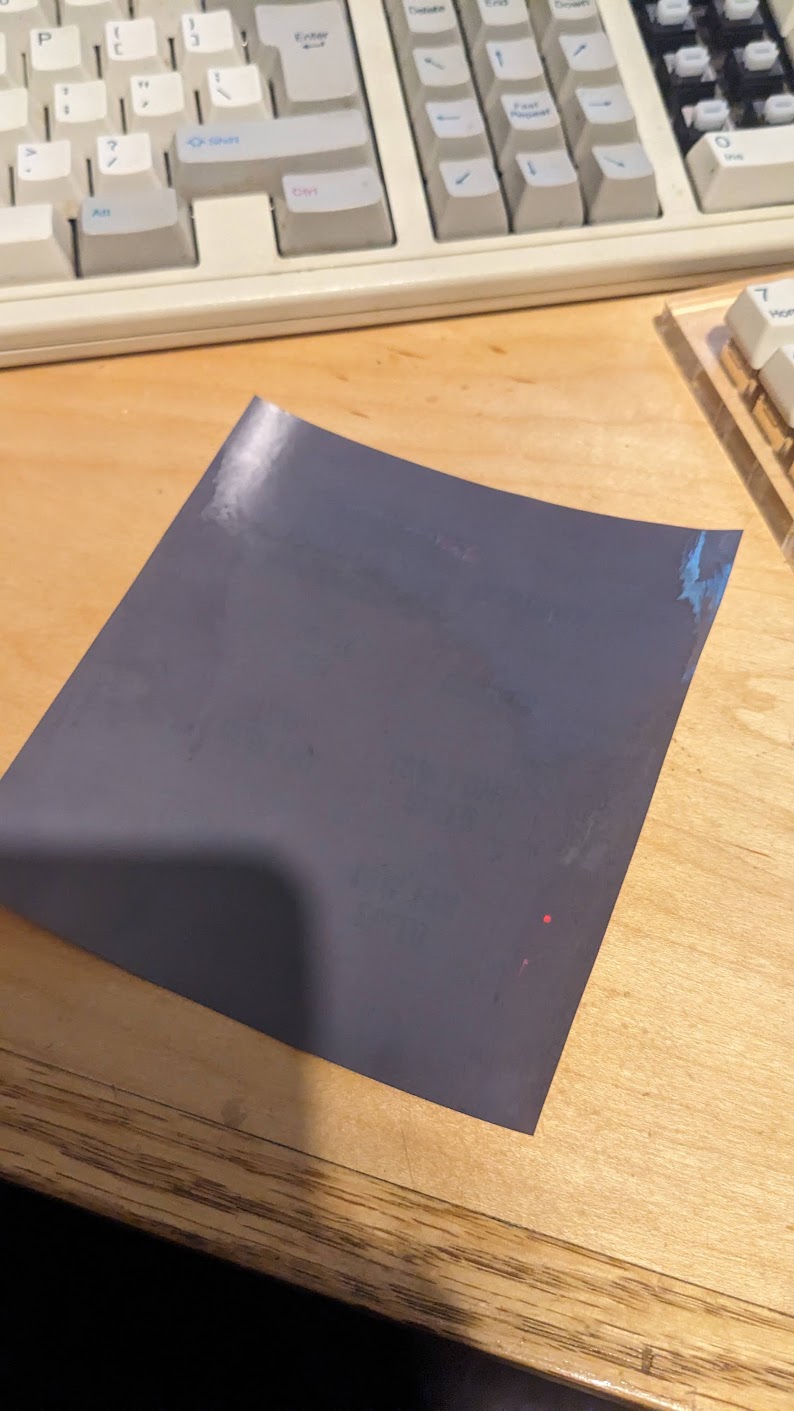
Second attempt I deciced to print them backwards, especially with lighter tint like 50%, you can see more through them so having the ink directly under the plastic made them too visible. but masking this way, all you see is dark grey until the light hits the paper
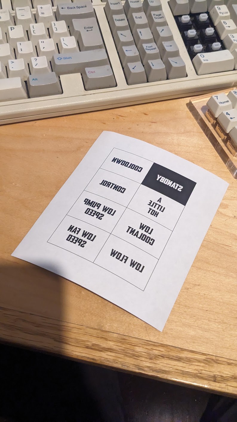
PCBs
I could have gotten away with just one but to make things easier for myself, I made two PCBs. One top and one bottom
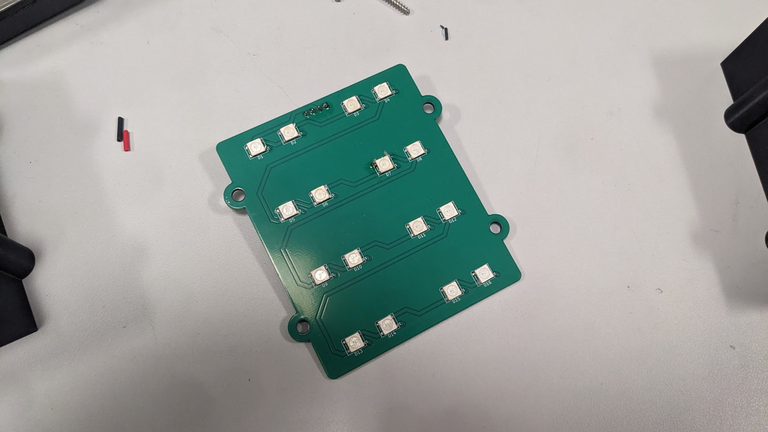
the bottom one was just an array of WS2812 LEDs arranged in a grid
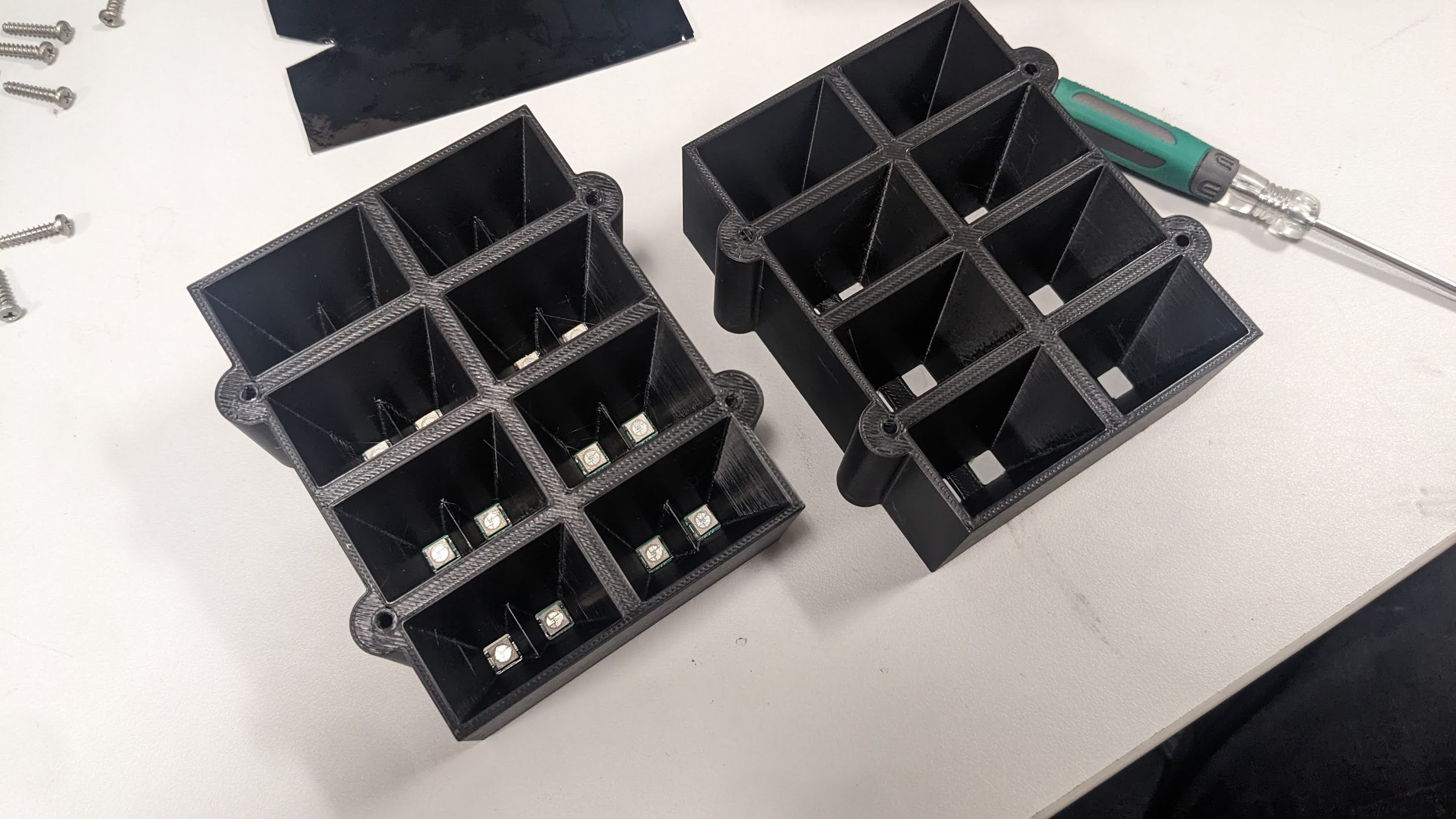
A 3d printed gaurd sits over the panel and gives you this little LED chunk.
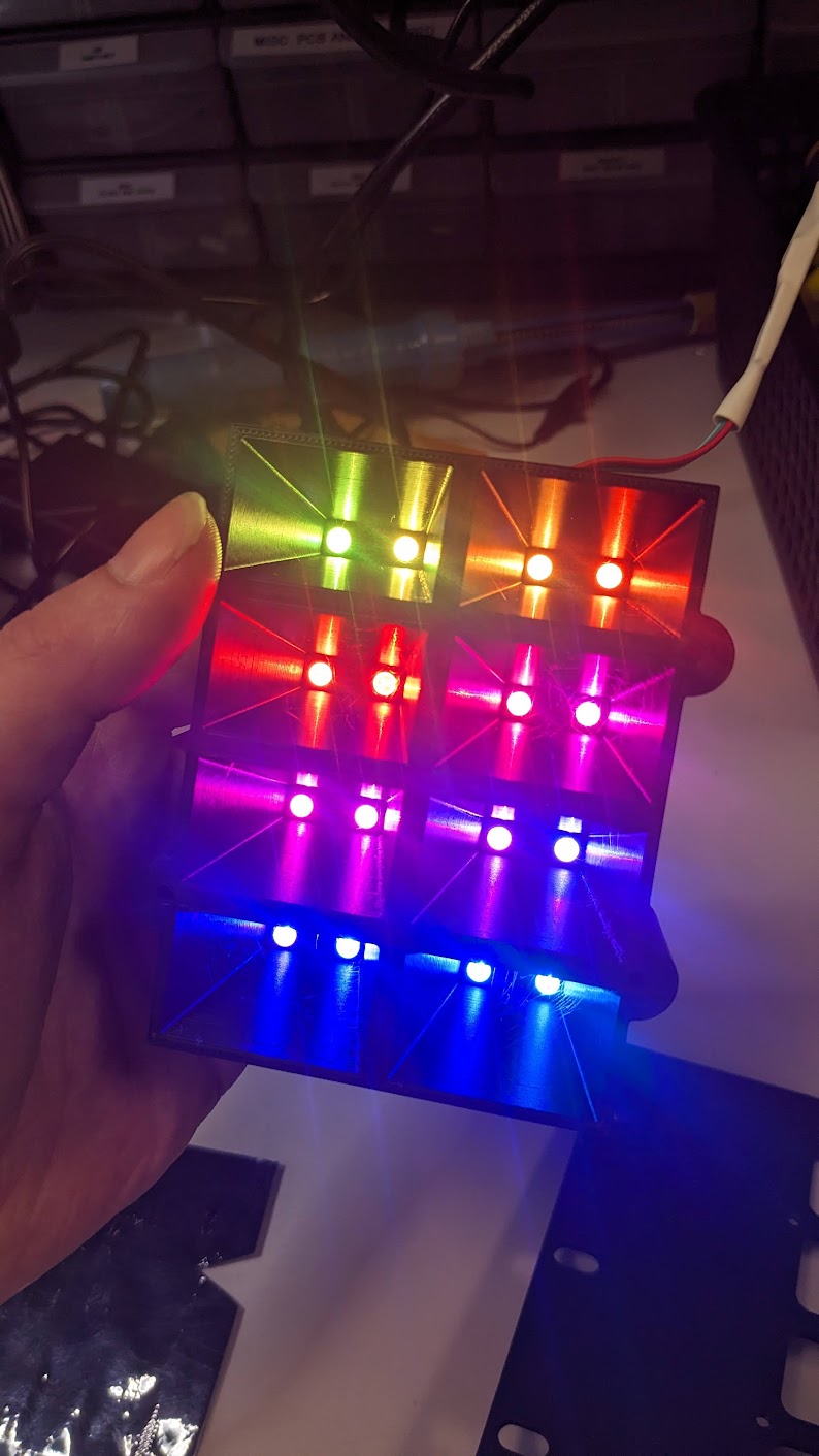
The top PCB is more interesting
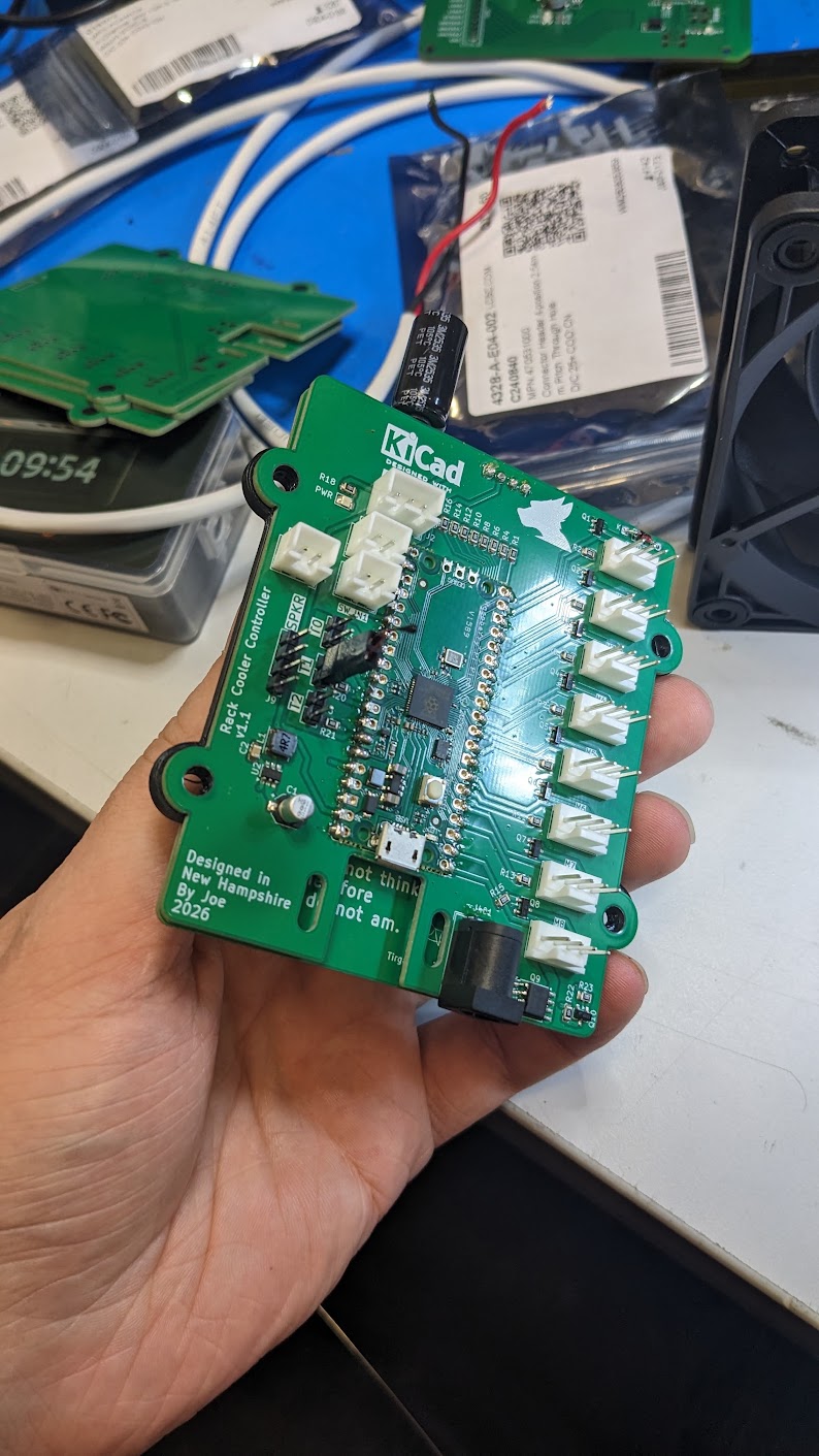
I was thinking of doing a direct rp2040 build but I still have so many leftover pico modules, and nobody will see it anyway.
8 fan drivers, three digital inputs, three temperature sensors and two LED driver outputs (one for the alphacool LEDs and one for the front panel grid)
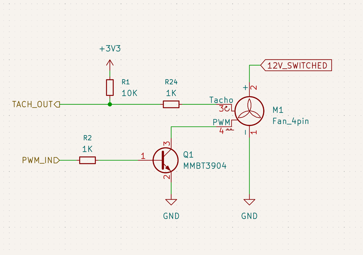
Everything else was pretty straightforward but I isolated my fans like this, running with my pulldown for the tach and using an npn to isolate the pico from the fan for PWM open collector
Firmware
The firmware is pretty simple, I did make a pair of pio assembly bits to perform some PWM and LED shifting faster.
.program ws2812

; We can set aside a pin (or more than one) for timing while running commands
.side_set 1

; WS2812/NeoPixel timing constants for 800kHz protocol (in PIO clock cycles):
; T1: Length of logic '1' high time after start of each bit (2 cycles)
; T2: Length of total bit time minus T3 (so T1+T2 = '1' time, '0' is T3+T2)
; T3: Initial low time after each bit (3 cycles)
.define public T1 2
.define public T2 5
.define public T3 3

.wrap_target
bitloop:
    ; For each bit, output the MSB of OSR to x, set output low for T3 cycles
    out x, 1       side 0 [T3 - 1]        ; Shift 1 bit from OSR to x. Output low for (T3) cycles.
    ; If the bit just shifted is '0', branch to do_zero after T1 cycles with output high;
    ; otherwise, fall through to do_one.
    jmp !x do_zero side 1 [T1 - 1]        ; If x==0 (the bit was 0), set output high and go to do_zero after T1 cycles.
do_one:
    ; Output high for (T2) cycles to represent a logic '1'
    jmp bitloop    side 1 [T2 - 1]
do_zero:
    ; Nothing for no-op
    nop            side 0 [T2 - 1]
.wrap
This is actually the same code i used on my capstone project
Software
Link to the software sourcecode
I really wanted two things when writing the software side, I know i wanted integration with sensors and ksystemstats and for that
I knew i'd need some sort of kernel mod.
I was inspired mostly by aquacomputer's kernel implementation. In theory i could have also modified my kernel but writing a dkms module seemed a lot less intrusive.
#define RACKDIST_USB_VID 0x1209
#define RACKDIST_USB_PID 0x0001
I used some of the testing/placeholder USB values. I could have also applied for my own but, I dont think a lot of people will be out there trying to recreate this. And if that ever did happen, they're easy to change in here!
All the code does is wait for hid messages to come over, filter them into the correct slots and call it good
static const struct hwmon_channel_info *const rackdist_info[] = {
    HWMON_CHANNEL_INFO(temp,
               HWMON_T_INPUT | HWMON_T_LABEL,
               HWMON_T_INPUT | HWMON_T_LABEL,
               HWMON_T_INPUT | HWMON_T_LABEL),
    HWMON_CHANNEL_INFO(fan,
               HWMON_F_INPUT | HWMON_F_LABEL,
               HWMON_F_INPUT | HWMON_F_LABEL,
               HWMON_F_INPUT | HWMON_F_LABEL,
               HWMON_F_INPUT | HWMON_F_LABEL,
               HWMON_F_INPUT | HWMON_F_LABEL,
               HWMON_F_INPUT | HWMON_F_LABEL,
               HWMON_F_INPUT | HWMON_F_LABEL,
               HWMON_F_INPUT | HWMON_F_LABEL),
    HWMON_CHANNEL_INFO(pwm,
               HWMON_PWM_INPUT, HWMON_PWM_INPUT, HWMON_PWM_INPUT,
               HWMON_PWM_INPUT, HWMON_PWM_INPUT, HWMON_PWM_INPUT,
               HWMON_PWM_INPUT, HWMON_PWM_INPUT),
    NULL
};
And thats pretty much it!
I'm glad to have gotten a first blogpost out, if you have any comments, I wanna hear them!
Comments
joe September 30, 2026
I cant read assembly